Built-In Metrology
Unlike conventional optical or e-beam lithography, the surface can be imaged in the STM without affectingthe resist layer, and using the same probe as used for writing. This allows for pattern alignment.
Hydrogen removal occurs during exposure at positive sample bias, with the tip moving very slowly across the surface. During imaging, the STM tip is set to negative sample bias, and moves much fasteracross the surface, so that the Si-H bonds are not affected.
Thus the surface can be imaged prior to writing, allowing alignment of the write vectors to the atomic lattice of the surface, and alignment to fiducial marks or to areas of previous patterning, for stitching between write fields.
By imaging the pattern a er writing, the quality of the lithographycan be checked, enabling some error correction, and as the actual written pattern including any errors can be imaged with atomic precision, the actual dimensions of developed nanostructures can be referred back to the original pattern.
Automated Fiducial Mark Alignment
Over larger distances, effects such as hysteresis, thermal dri and uncorrected creep can still cause errors in the tip position.
In particular, hysteresis errors increase quadratically with jump size. For a movement of several μm, the hysteresis errors can be hundreds of nm.
Therefore, Scanz has the capability to search for, identify, and automatically align to fiducial marks on the surface, so that accumulated position errors can be zeroed. A fiducial realignment step can be included in a larger script, so that operator intervention is not required.
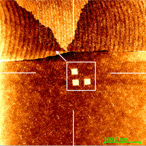
A fiducial mark is located, by comparison to aprevious image of the mark taken after writing.
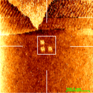
The scan centre is relocated to the fiducial mark, even using low resolution, fast imaging.
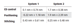
Summary of Lithography Test Data