A new leap forward in STM design: real-time position correction
|
For more information, or to request a quote, contact us at info@zyvexlabs.comOr you can submit your name and email below. |
Capabilities:
- Removal of creep-related xy and z drift – Rapid tip settling for slow IV curves.
- Remove image distortions – no forward/backward scan offset, correct dimensions.
- Accurate navigation across the surface – 10 nm error on 5 µm jump.
- Jump precisely to point of interest for imaging or spectroscopy.
- Real-time correction of creep and hysteresis behind the scenes, without modification.
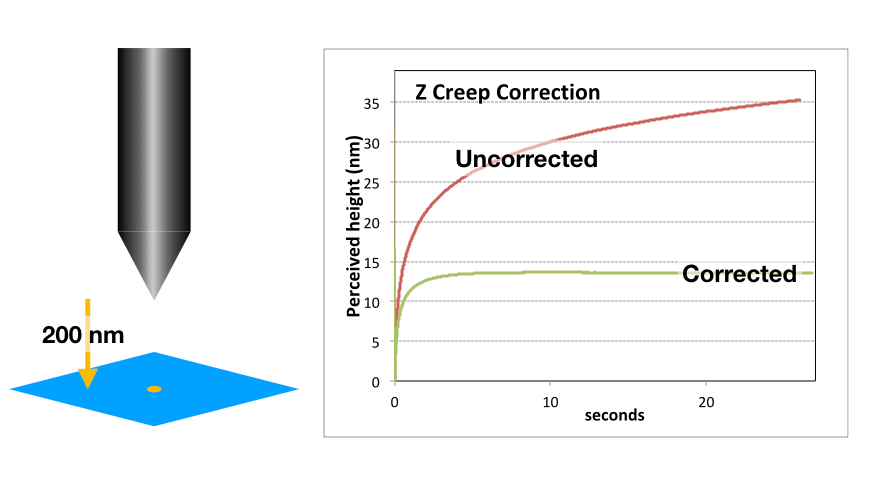 |
Correcting Z creep during landing The z voltage is plotted for uncorrected creep, and with creep correction applied. With uncorrected creep, the z voltage is still changing quickly after 30 s (and for many minutes thereafter), while the creep correction gives almost zero motion after less than 10s (residual z motion at 20 s is about 4 nm/h). This allows for much shorter settling times after movement before performing spectroscopy. |
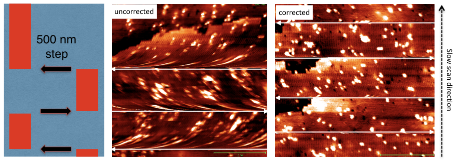
| Correcting XY creep during scanning. Sideways jumps of 500 nm during scanning at the positions marked by arrows result in curved surface features due to the curved tip trajectory caused by creep. With the Zyvex Smart Positioning System, large jumps can be made without these distortions. |
 |
|
Accurate Navigation Across the Surface
|
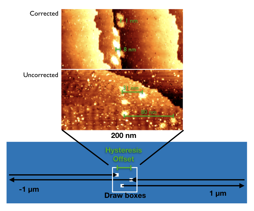
With creep and hysteresis correction, it is possible to make large movements across the surface and return to the original location. In this test, the tip makes large jumps back and forth, and draws a box at each location. The hysteresis offset is measured as the distance between the second and third boxes. With creep and hysteresis correction, the offset can be reduced to zero. Uncorrected In the first set, the gap between boxes after a 1 μm jump is 80 nm, which is a mixture of creep and hysteresis. In the second set, the top waited a few minutes before drawing a box, and the gap is now 30 nm, which is mainly hysteresis. Corrected A similar data set after applying creep and hysteresis correction. Now the boxes are all almost perfectly aligned, even after a 1μm jump. Hysteresis on 5 μm jumps is expected to be ca. 700 nm, because it scales quadratically. In tests, the residual error for 5 μm jumps is about 10 nm, a 98% correction. |
|
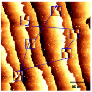
Jump Precisely to Region of Interest In many situations, it is desirable to take a quick, low-resolution image of a large area, and then zoom in to small areas to obtain more detailed images. In this example, step edges in the small inset images taken in the order indicated by the arrows line up well with the original large image. |
 |
Remove Image Distortions – No Forward/Backward Scan Offset
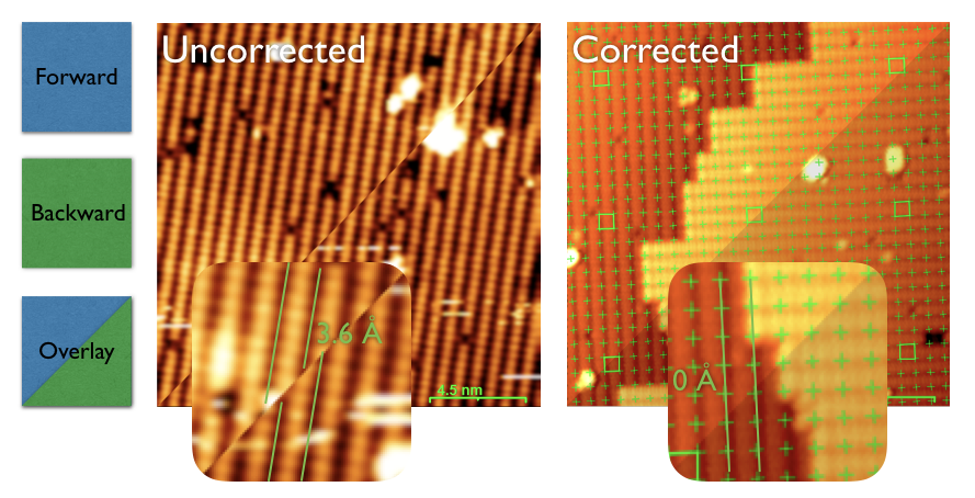
Creep also occurs on the timescale of STM scanning. Without creep correction, there is an offset between Forward and Backward scans, here 3.6 Å , ½ a dimer row. With creep correction applied, the offset is zero. Without fast creep correction, the forward/reverse offset means the tip is never where you think it is. Fast creep during scanning also affects the measured lattice parameter, so metrology of surface features will be incorrect.
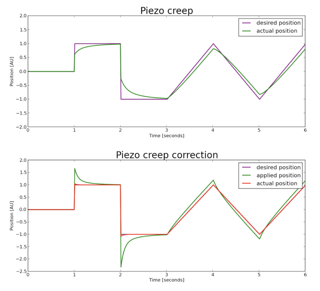
| How it Works Piezo creep results in an undershoot of real position vs. desired position. The actual position is path and velocity-dependent. Realtime creep correction is therefore necessary to compensate for each motion as it occurs. A voltage overshoot is applied to correct the position undershoot. The applied voltage is set to decay with time to match the expected creep, keeping the tip at the correct real position. The creep must be calibrated for each scanner, but is around 10% of the motion. The CHC box receives the piezo voltages from the digital controller, modifies them to correct for creep and hysteresis, and then passes the corrected voltages on to the piezo drivers. In this way, the corrections are achieved without any required modification of the STM control system. |
 |