If you sell or use open-loop piezoelectric actuators, you or your customers experience the positional errors created by creep and hysteresis.
For decades, many have attempted to correct the creep and hysteresis errors in piezo actuators. However, none have worked well enough to be used in high precision motion applications, like Scanning Tunneling Microscopes.
We have addressed this problem without the expense of a closed-loop system.
• Zyvex Labs has developed a software that reduces creep and hysteresis positional errors by over an order of magnitude.
• We call our solution “Creep and Hysteresis Correction (CHCTM)”.
• This has enabled us to achieve automated Atomically Precise lithography.
All of this happens in our proprietary software with digital representations of the analog voltage that is used to drive the piezo actuators.
Ways to Integrate CHS into your application
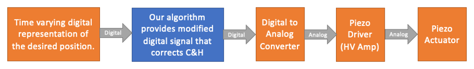
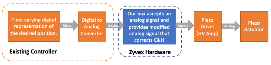
Software: The easiest approach is to work with the digital signal in a controller that represents the time-varying position desired for an axis of a piezo actuator. Our software can modify that signal in a way that corrects for C&H. The corrected digital signal is then sent to a digital to analog converter within the controller. Typically, that low-level analog voltage is then amplified by a piezo driver that is sent to the piezo actuators.
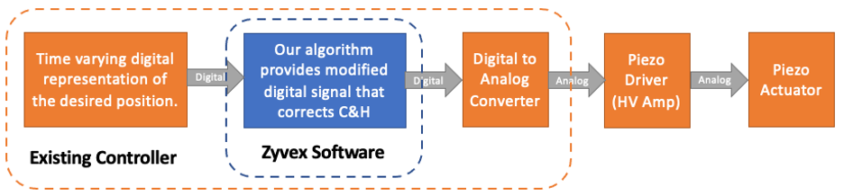
If a nano-motion controller has sufficient computing power, we may be able to simply provide software that achieves CHC. If the application requires a relatively high bandwidth in the piezo signal, the controller must have low latency in updating the control signal. This is the most cost-effective approach.
Hardware Options:
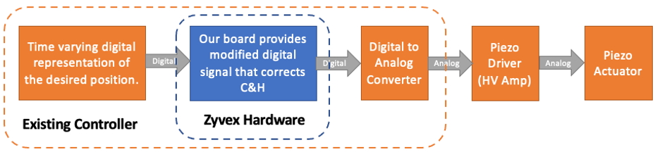
PCB to interface with existing units: If the controller lacks the computational resources or does not have sufficiently low latency but has empty circuit board slots, we could provide a board that intercepts the digital signal and feeds it to the controller’s DAC which provides the analog signal to the piezo drivers. Boards that handle multiple axes are possible. We could develop and sell such a part.
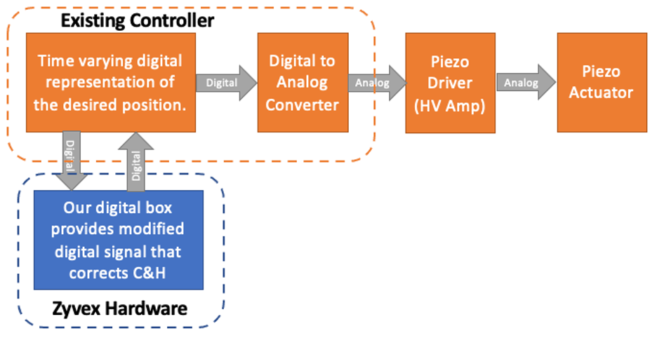
External interface with existing units: If the controller lacks room, power, and or internal connections, but could be modified to provide digital out and input connections, could interface with an external box that could modify the digital signal to effect creep and hysteresis. We could develop and sell such a part with multi-axis options.
More Hardware Options: Another possible configuration is an external box that accepts an analog voltage signal, converts to digital, executes our algorithm, and converts back to analog. This is a more expensive solution as it has the additional costs of analog to digital and digital to analog converters but could be done if required. We could develop and sell such a part.
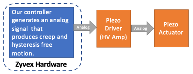
A Zyvex Controller: Finally, we are contemplating creating a Zyvex Nanopositioning Controller for piezo actuators. We have already done so with our ZyVector Scanning Tunneling Microscope controller. If there is a need, we could develop a specialized controller for you that could range from a controller that simply accepted a digital stream that represented desired motion of piezo actuators in one or more axes, to a much more sophisticated controller that generated a programable or specific desired motion.
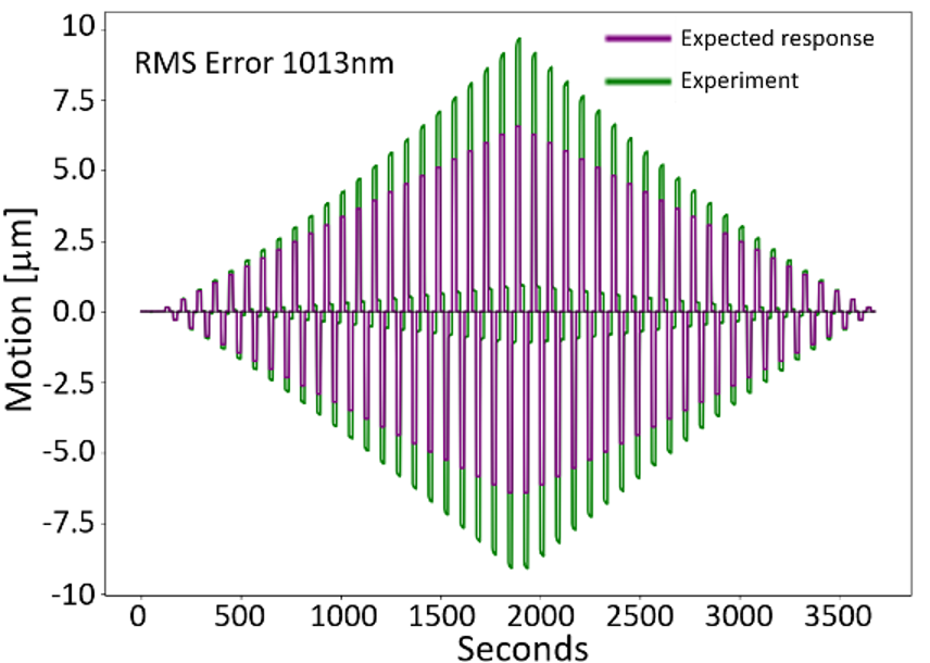
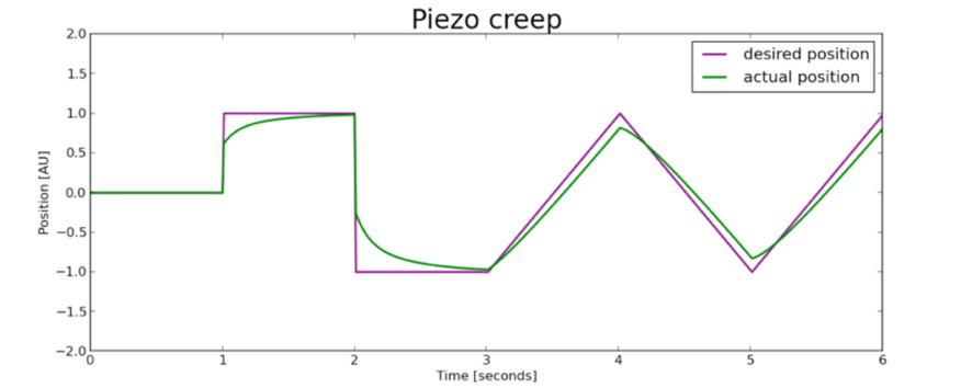
Creep is a time varying lag in motion whose magnitude is proportional (roughly 10%) of the desired motion. Hysteresis is a non-time varying position error whose magnitude is quadratic with the distance moved. The data below shows the measured motion (in green) compared to the expected linear response to the desired motion. Both creep and hysteresis errors are evident in this graph. The hysteresis is the overshoot (moving away from zero) and undershoot (moving back toward zero) as seen in the experimental (green) data. The creep is continued motion away from zero when moving away from zero and continued motion toward zero when moving toward zero. The total Root Mean Square (RMS) error represented in this actual versus desired motion is 1013nm.
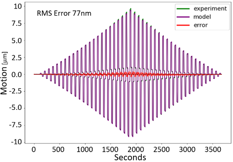
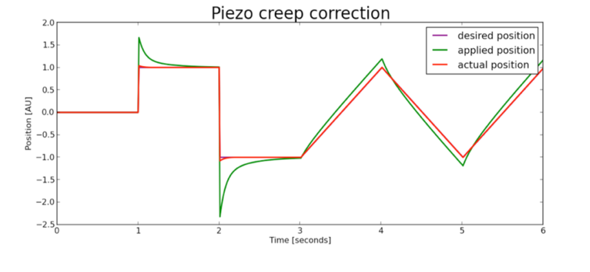
Our proprietary software predicts the effect of both creep and hysteresis. The following graph is the same experimental data (green) from the graph above as well as our software model’s prediction of the motion. As you can see in the model’s (purple) strong overlap with the experimental (green), the model fits the data very well. The error between the model and experimental data is shown in red. The RMS error is reduced from 1013nm to 77nm.
With a predictive model and knowledge of the desired time-varying displacement, we can correct the applied voltage to achieve the desired response. The figure below is not real data but does represent the creep correction scheme. First, we show the desired motion and the actual motion with uncorrected creep.
Because we can calculate the piezo actuator’s time-varying response, we can adjust the voltage signal so that the resulting motion matches the desired position much more accurately.
Finally, we present a demonstration of our CHCTM technology on the very demanding platform of Scanning Tunneling Microscopy which uses piezo actuators in X, Y, and Z. The X and Y axes are in the plane of the sample’s surface and the Z-axis measures the distance normal to the sample’s surface. We note that our method requires calibration, but in our experience, the calibration is stable over long periods of time and is not very temperature-dependent.
While creep and hysteresis are always present, they are most obvious when “larger” moves are made. For instance, if we move an STM tip 500nm in one direction, it will move ~90% in the desired direction, moving quickly at first but continuously slowing the amount of creep; it will take hours before all perceptible motion stops.
In the first example, we move the tip 500nm to the right (X direction) and then scan only in the X-direction. (Normally we would scan in an X-Y raster, but the repeated scan in only X makes the creep more obvious.)
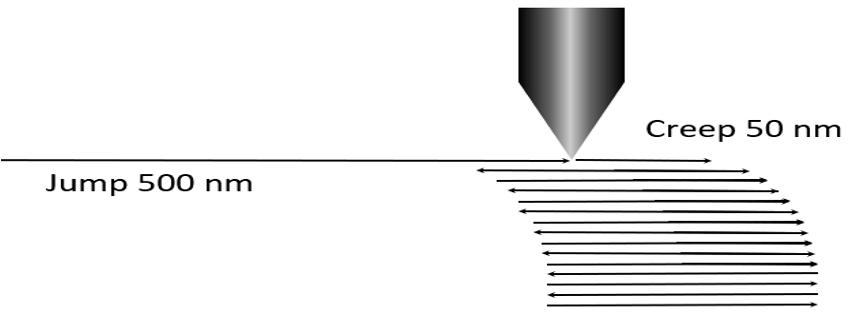
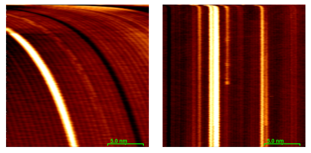
After a 500nm jump and scanning only in X for 200s, the curvature on the left is an uncorrected creep. On the right, the vertical lines indicate corrected creep.
Creep and hysteresis in the Z direction are usually not very evident in STM images because the current feedback loop is constantly moving the tip to keep the current constant. Therefore, the tip maintains a fairly constant distance from the surface in spite of the undesired effects of C&H.
However even with the current feedback loop on, with the tip stable in X and Y we can monitor the tips Z-creep by seeing how the signal to the Z-axis changes to maintain the constant current. This motion is correcting for creep.
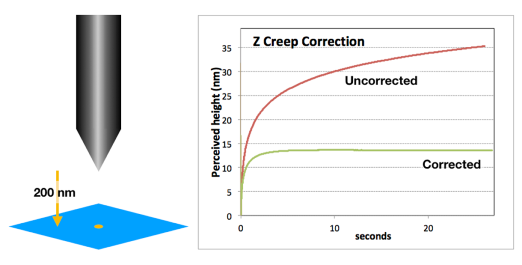
In the experiment depicted below, after dropping 200nm to get in tunneling range, without CHC the control loop must back the tip up by ~20nm in 20S. With CHC active, as expected, the tip shows very little Z-motion.
If you would like to explore the advantages of our proprietary creep and hysteresis correction technology, please contact us.
John N. Randall – CEO Zyvex Labs
(214) 641-6458